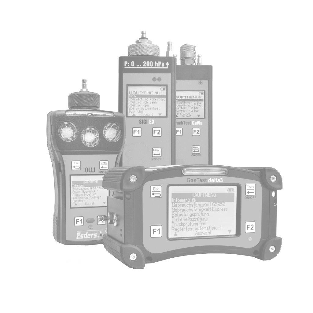
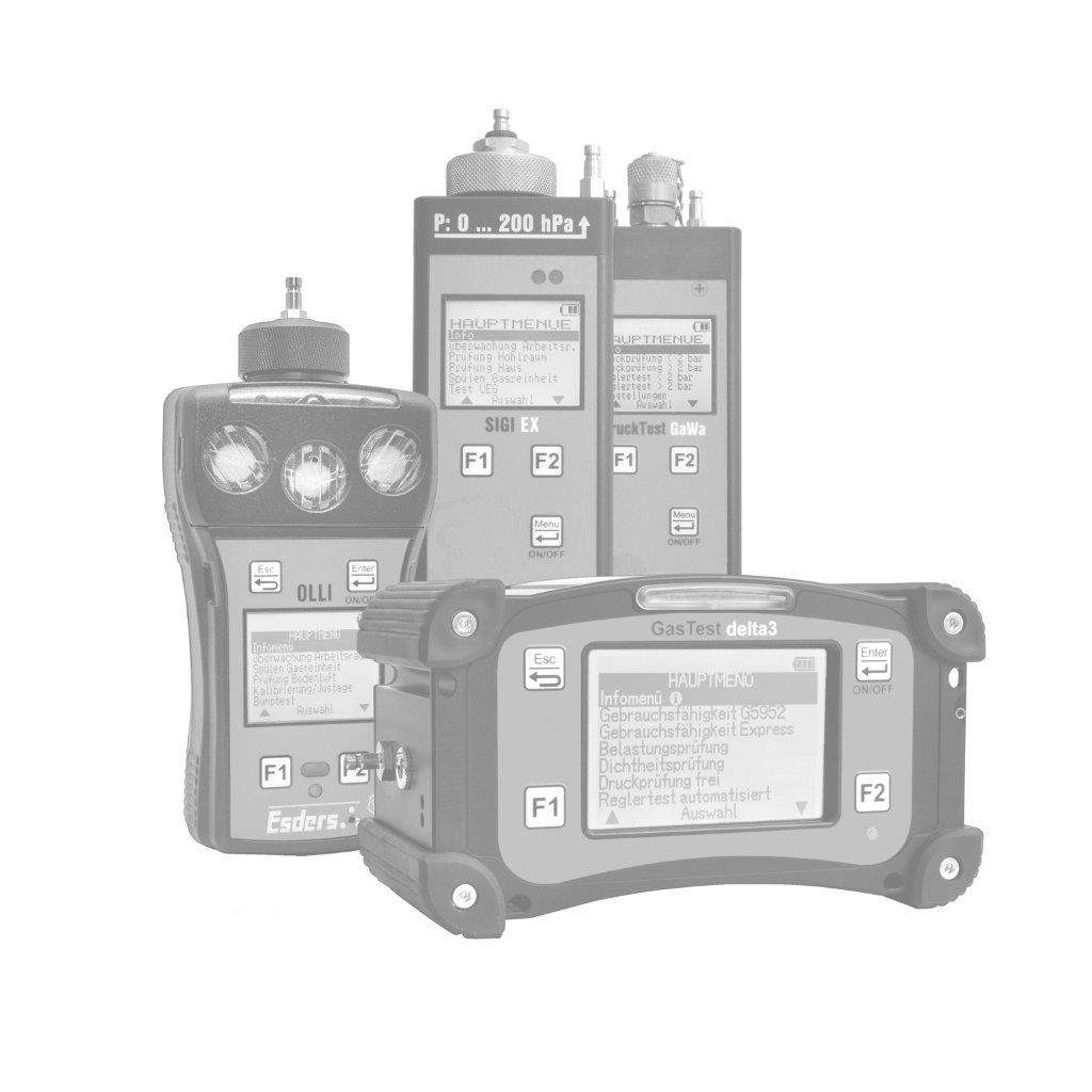
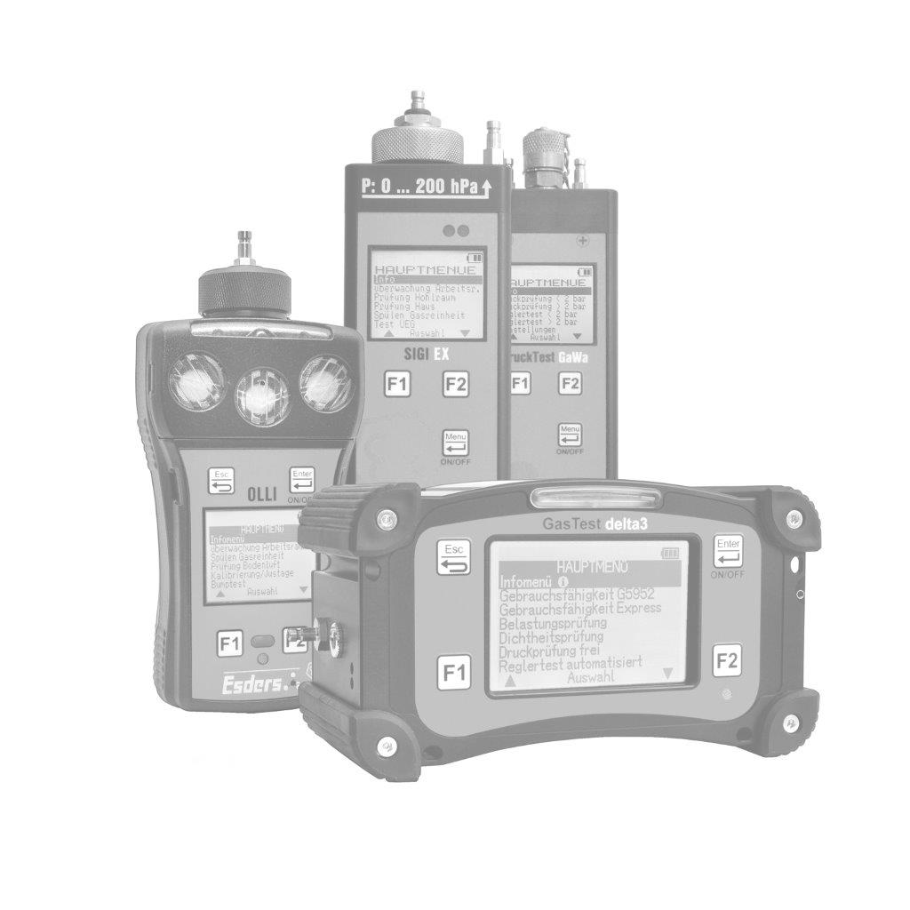
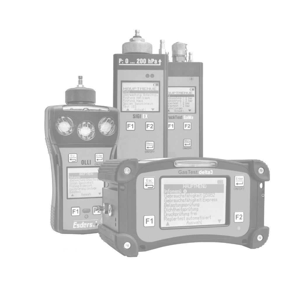
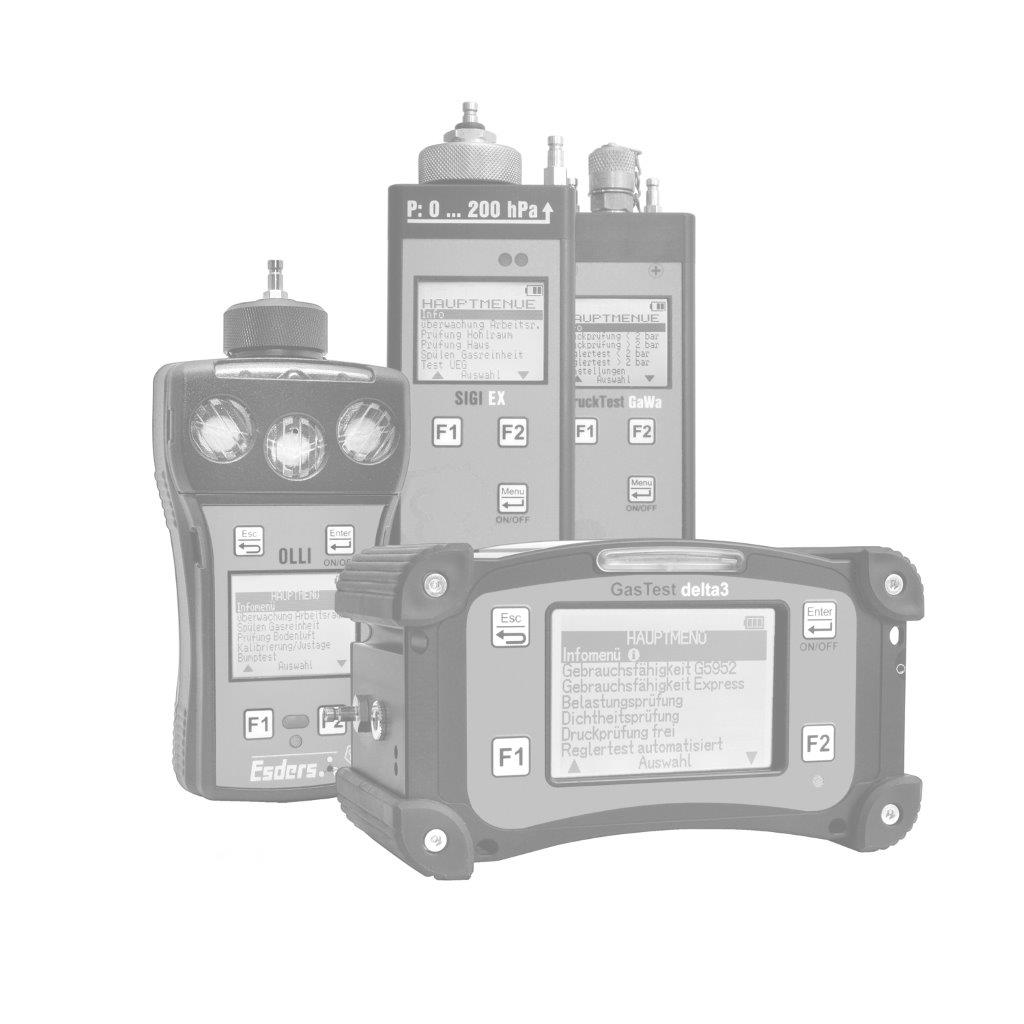
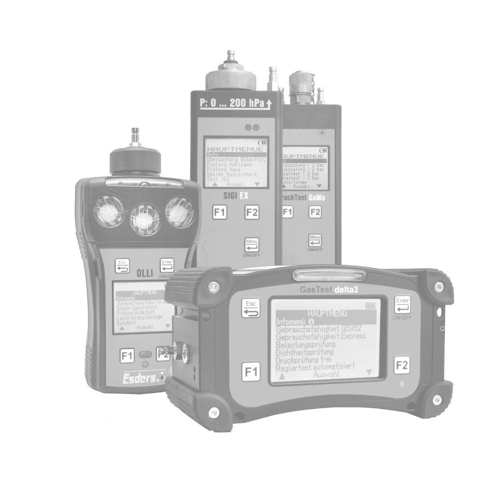
In our blog post on the subject of serviceability, we dealt with the theoretical background. In this blog post we will now describe the practical implementation of such a test and explain what needs to be taken into account. Depending on the leakage measuring device used (see different classes in the blog post), the actual practical implementation may vary. In the following, we describe the use of a leakage meter of class L with a flow sensor for the direct measurement of the gas leakage quantity, using our GasTest delta3 as an example.
Test medium
Since the leakage quantity is measured directly with the GasTest delta3 and not calculated, it is necessary that any leakage in the pipe system is “fed” during the measurement.
As a rule, the fuel gas present in the pipeline system in operation is used as the test medium.
A gas balloon installed in the lid compartment of the case is used as a gas reservoir during the test in the GasTest delta3.
Testing with air instead of fuel gas is also possible in principle, but it increases the effort on site considerably, as the pipeline system to be must first be cleared of gas (see DGUV Regulation 100-500, Chapter 2.31 for the term “without gas”) and then re-filled with gas after the test. In addition, problems may arise when the gas appliances are put back into operation. Oxygen is not permitted as a test medium, nor is a mixture of fuel gas and air.
Suitable connection to the gas installation
Before starting the test, a suitable connection to the gas installation must be determined. There are various possibilities that must be checked on site or in advance. If necessary, the specialist company carrying out the work also has corresponding work instructions that specify where the connection to the gas installation must be made.
If the serviceability test takes place, for example, in the context of a planned meter change, it makes sense to use the meter connection as a test opening, since the meter has to be dismantled anyway.
Other suitable connection points can be measuring openings in/on the gas pressure regulator or on the gas appliance fitting or – if present – test openings built into the pipe system. These can be used with suitable adapters and seals.
For further information regarding test & measurement openings in the gas installation, we have a short blog post here. In this post, we describe the testing via the meter connection.
Connection of the meter
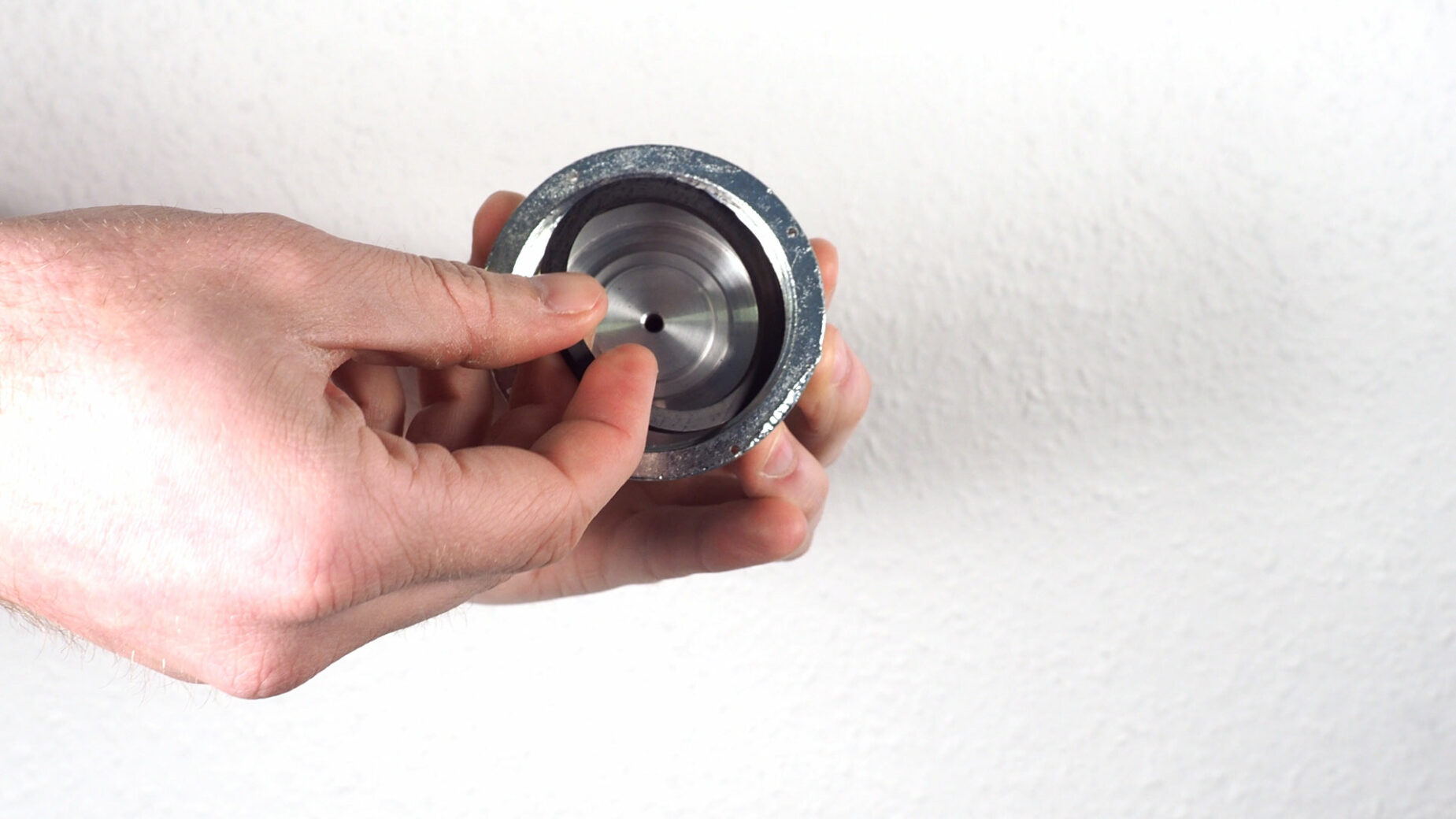
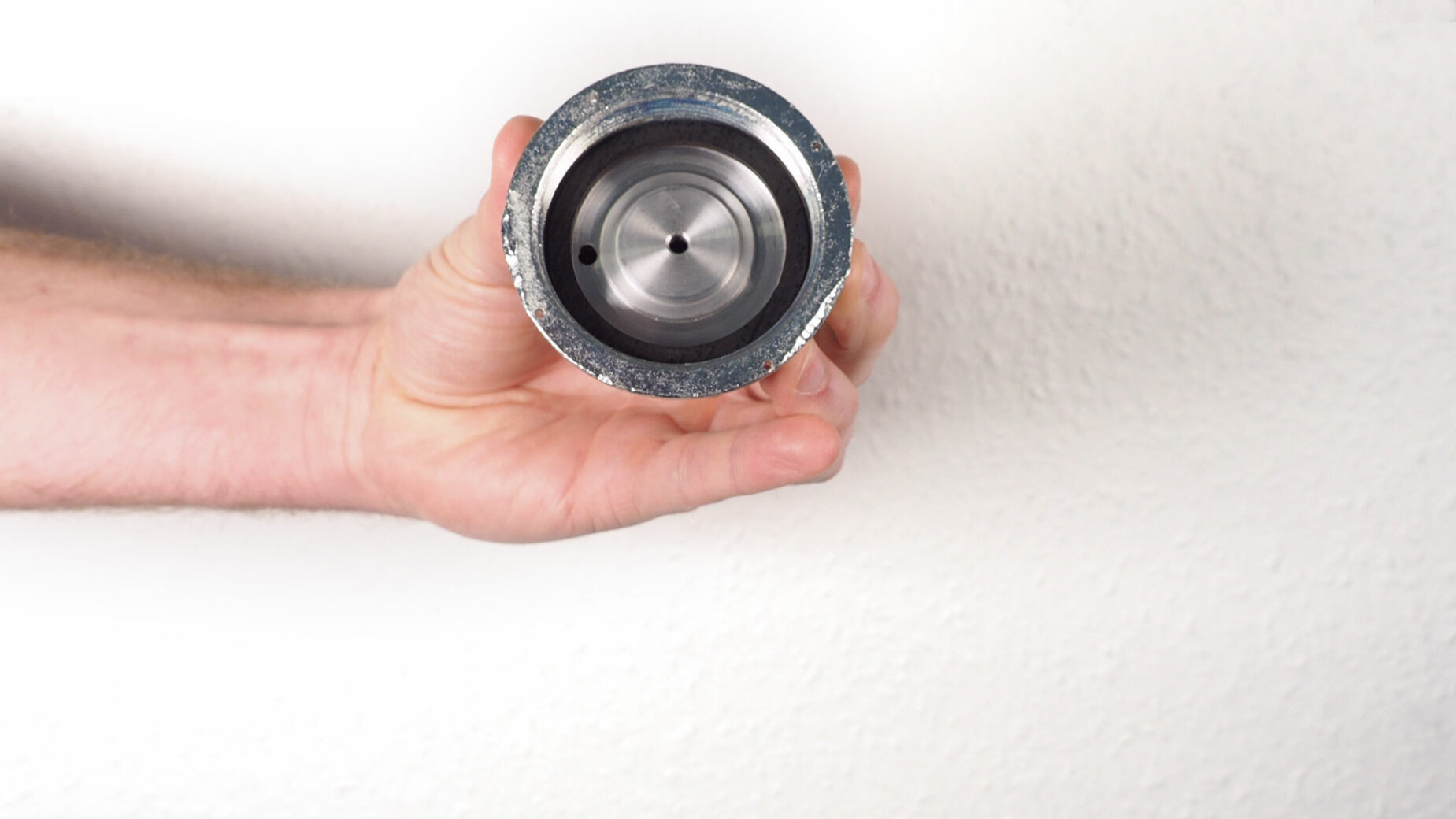
When connecting the meter to a single-pipe meter fitting, a so-called overflow seal can be inserted into the test adapter.
In the case of two-pipe meters, the fitting pieces for the meter inlet and outlet can be connected to the meter at the same time using the appropriate accessories (adapter and Y-hose). This means that in both cases it is possible to feed from the meter connection backwards to the gas pressure regulator (GPR) or the main shut-off device (from German Hauptabsperreinrichtung = HAE) and forwards to the gas boiler, and various pipe sections upstream and downstream of the gas meter (e.g. riser pipe, distribution pipe, consumption pipe) can be tested simultaneously. This minimises the testing effort considerably and saves time.
In principle, a leakage measurement independent of the gas network is recommended in order to exclude the influence of possible fluctuations in the local gas network during the test. For this purpose, the HAE is closed after the measuring device has delivered some gas into the gas balloon already mentioned. Depending on the structure and geometry of the pipeline system, minor fluctuations may nevertheless occur during the measurement. These are often caused by the influence of the GPR on the downstream pipe system or a part of the pipe between the HAE and GPR that is under mains pressure. This can usually be remedied by setting the test pressure slightly above the operating pressure (e.g. 27 mbar). In this way, the GPR is “sealed” from behind and a possible undesired influence is excluded.
It is also important that all consumable devices in the house are closed to avoid gas leaks during the test and thereby falsifying the measurement results.
Reference operating pressure
The connection points or test openings used should be located behind the gas pressure control that is usually present, since the leakage quantity measurement is usually carried out at a test pressure of 23 mbar or – depending on the measuring device used – slightly above this.
In the latter case, the determined gas leakage quantity is converted to the so-called “reference operating pressure” of 23 mbar. This is done automatically in the GasTest delta3.
An exception is a pipeline system that is operated with increased low pressure of, for example, 40 mbar. This is often the case with meter regulators (editor’s note: a gas pressure regulator integrated into the gas meter). If this operating pressure is above 30 mbar, it must also be used as the reference operating pressure (instead of the 23 mbar usually used).
The GasTest delta3 automatically converts the determined leakage quantity to the correct reference operating pressure even in this case.
Serviceability test with the GasTest delta3 - Part 1: Preparation for leakage measurement
Once the preparation for leakage measurement is complete and the measuring device is connected to the gas installation, the test can begin. In the case of the GasTest delta3, the first step is to decide which specifications should be used to test the pipeline system. There are two possibilities:
- Testing and evaluation according to DVGW regulations with exact specifications for the adjustment & test duration as well as permissible fluctuations of the pressure and the leakage quantity (menu item “Serviceability G5952”).
- Testing and evaluation according to times and limits that can be freely set in the unit (menu item “Express serviceability”)
In the latter case, the qualified person decides on suitable times based on his knowledge and experience on site and evaluates the stability of the measurement. At the beginning of the selected test sequence, the specialist must set the desired test pressure and the test medium on the device and then start the sequence. When testing according to DVGW regulations, the pipe volume of the pipeline system must also be entered in fixed steps (< 100 l or < 200 l).
The measuring device now runs through the test as far as possible automatically and informs the technician about all steps that have been carried out or need to be carried out.
Serviceability test with the GasTest delta3 - Part 2: Carrying out the leakage quantity measurement
Depending on the size of the pipeline system to be tested, a short stabilisation phase takes place before the actual test, consisting of the adjustment and measurement phase. If the measured values fluctuate strongly or permanently during this first phase, a proper test cannot be carried out. The causes for this can be different and should be analysed by the performing specialist on site. Some examples:
- Has the device been started correctly and according to the specifications in the operating instructions (e.g. with gas balloon connected)?
- Are the accessories used intact and leak-free (adapters, hoses, etc.)?
- Are the test adapters incl. seals tightened firmly enough (“hand-tightening” is sufficient)?
- Is the HAE closed?
- Have the ambient conditions in the room or on the pipeline system changed during the test (e.g. temperature influence due to sunlight, draught, etc.)?
- Is the system to be tested too large (total volume should not exceed 200 l)?
In the last example, especially if the pipeline volume is excessively large, a section-by-section test is recommended.
The TRGI gives the example of a building with a floor supply, in which the individual flats may be divided into separate test sections. The separation often helps to carry out a stable test and to be able to better localise a possible leakage. The criteria for assessing serviceability mentioned in the blog post then apply individually to each test section.
If the gas from the gas bladder installed in the case is not sufficient to feed a larger leak for the duration of the test, an additional external gas bladder can be connected to the case.
Documentation
If the test has been carried out successfully, the measurement device displays a summary of the results at the end.
The user can now enter further information, e.g. the assessment of the visible condition of the system and the functionality of the components in the measuring device and save it together with the measurement results. This result is a complete documentation of the entire serviceability test, as required by TRGI.
This data can be read out from the meter using a smartphone or tablet via the Esders Connect app and sent to up to three email addresses at the same time.
This means that the documentation of the test, is virtually in real time, in the office for billing with the client or for archiving and can also be handed over directly and digitally to the client. A printout of the test results via a suitable thermal printer is of course also possible.
Regular testing of the pipeline system for serviceability also helps to meet the requirements of the planned EU methane regulation to reduce methane emissions.
Serviceability test with the GasTest delta3 - Part 3: Documentation
Device technology and accessories
Article:
- 211200 GasTest delta3
Charging & Storage
- 202002 Charger 230 V
- 202003 Car charger 12 V
- 212107 Carrying case with balloon & charging connection
Connection Accessories
- 312100 Test plug conic ½“ with ball valve
- 312101 Test plug conic ¾“ with ball valve
- 312102 Test plug conic 1“ with ball valve
- 312018 Test cap DN 25 (for single-pipe meter)
- 312025 Test cap DN 40 (for single-pipe meter)
- 312166 Adapter screw connector 1 ¼“ (for 2-pipe gas meters)
- 312167 Adapter screw connector 1 ¾“ (for 2-pipe gas meters)
- 312168 Adapter screw connector 2“ (for 2-pipe gas meters)
- 212021 Pressure resistant Y-connector (for 2-pipe gas meters)
- 312089 Connection hose
Additional gas balloon/bladder for large pipelines and leakages

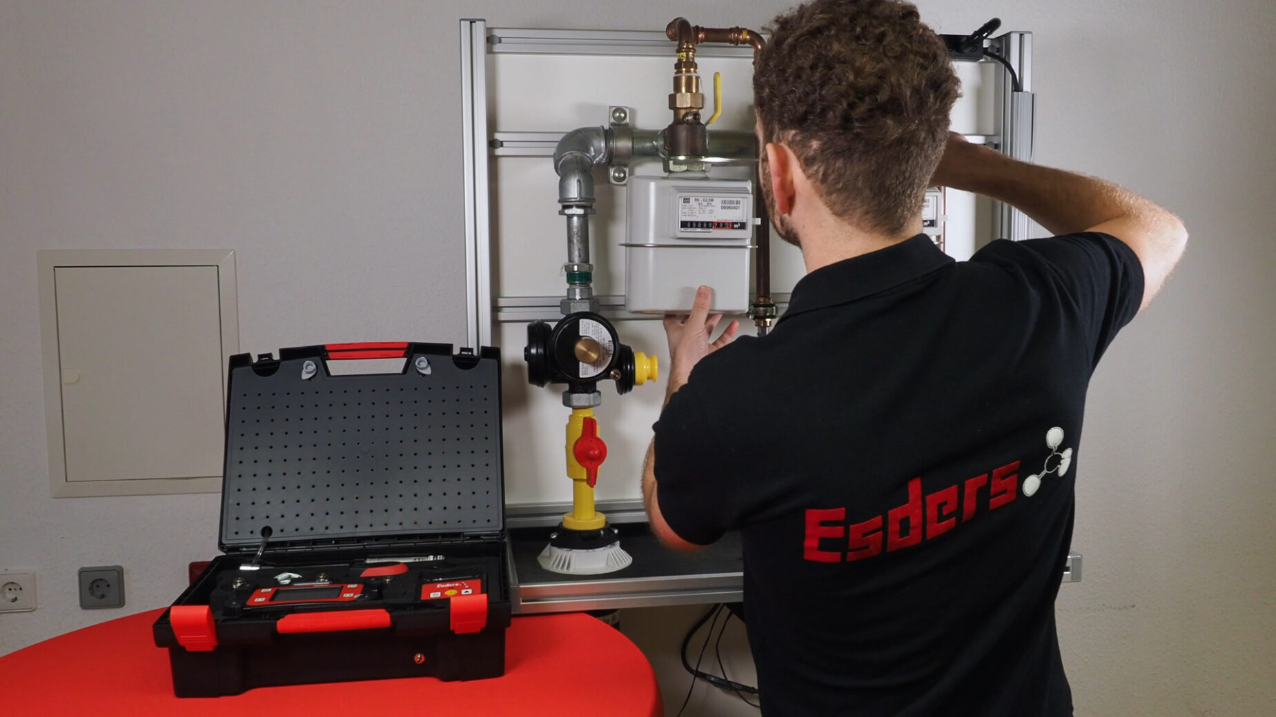


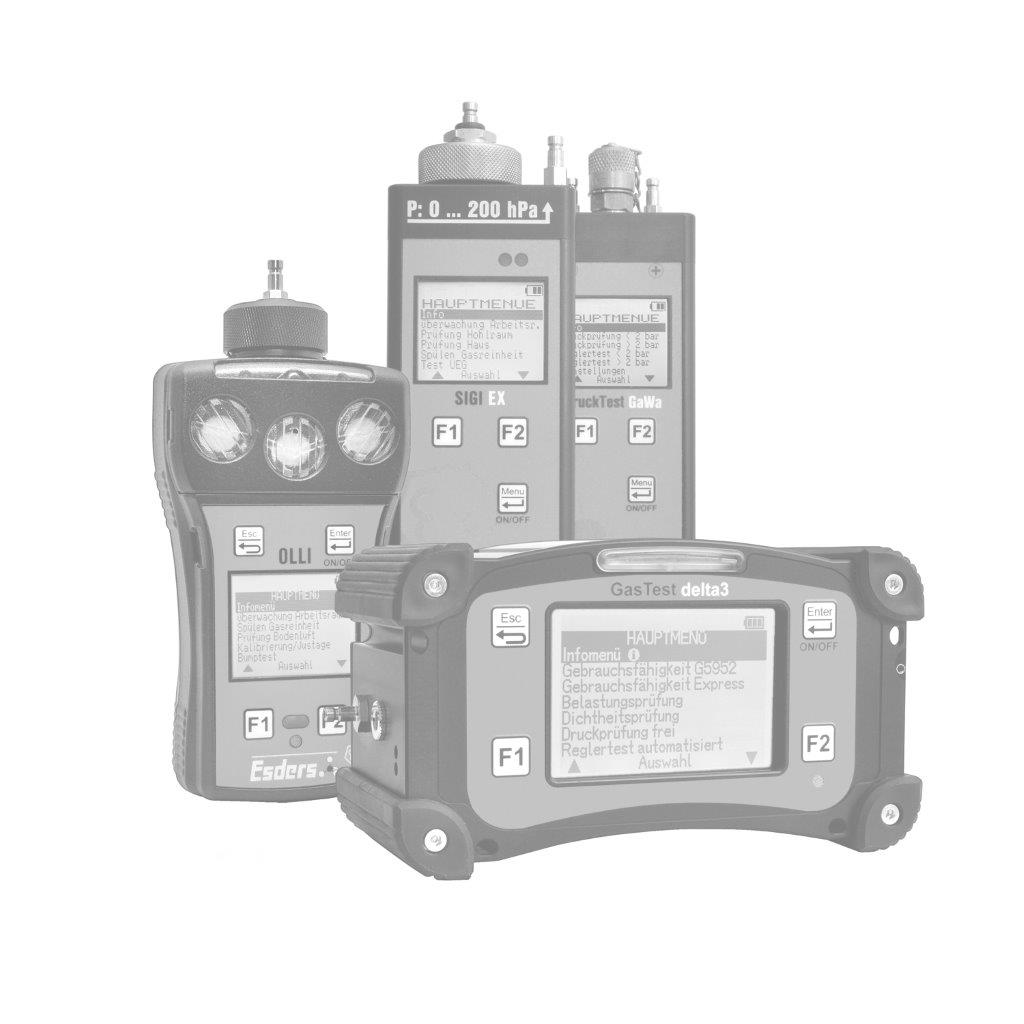.jpg?width=100)
.jpg?width=100)
.jpg?width=100)
.jpg?width=100)
.jpg?width=100)
.jpg?width=100)
.jpg?width=100)
.jpg?width=100)
.jpg?width=100)
.jpg?width=100)
.jpg?width=100)
.jpg?width=100)
.jpg?width=100)
.jpg?width=100)
.jpg?width=100)
.jpg?width=100)